Assesment and Re-Design of VIROMAX (Self Propelled Kid’s Ride)
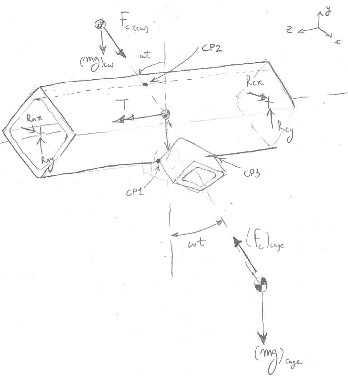
Figure 1: Viromax front view
Preface
In 1987, the Richer brothers came up with a revolutionary concept for a super swing. It all started with one prototype built in their own backyard and this super swing grew in popularity ever since. Ten years later, in 1997, a new and improved swing was born. This new swing was named VIROMAX. The VIROMAX was then brought to various different events across Québec and was featured in many articles. In June 2000, the owners of VIROMAX were invited to the first Salon des Inventions du Québec à Montréal, headed by Mr. Daniel Paquette of the Inventarium. At this event, the Richer brothers won the public’s choice award and it was a dream come true. VIROMAX is a small company, but they have big dreams and big plans for the future.
Introduction
This project summarizes the fatigue analysis of the critical components of the VIROMAX, specifically the main shaft, secondary shaft, bolted joints and bearings. Based on the results components were re-designed and the final configuration of the ride will be presented.
In a team of four, our goal was to assess the overdesigned components and re-design (if necessary) the self-propelled kid’s ride VIROMAX. The safety factors of the main components were central to establishing where we could save weight.
The main components that need assessment were:
- Main shaft (1st axis of rotation)
- Secondary shaft (2nd axis or rotation)
- Bolted joints
- Bearings
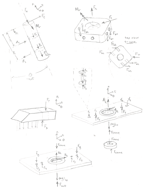
Figure 1: Viromax front view
VIROMAX has given some information regarding the components above. The maximum velocity recorded of the main shaft is 60 RPM. The maximum velocity of the second shaft is 150 RPM. The maximum weight considered is 300 lbm. Operating temperature is from -40°C to +40°C. In addition, a Bill of Materials was provided along with some 2D CAD drawings and a 3D SolidWorks assembly. Lastly, we were told to assume infinite life and we were given a reliability factor of 99%.
Tools
- Solid Works
- MATLAB
Secondary shaft
A static analysis and a failure analysis were performed on the secondary shaft to ensure its design was reliable and safe. The analysis included free body diagrams, equations of motion, validating assumptions, approaches and applying numerical methods.
Figure 5: Views of Secondary Shaft
Static Analysis
First, the loading for the secondary shaft under stationary conditions was considered. This consisted of a simple application of the static safety factor equation for the stress induced by the weight of the cage and 300 lbm person (a conservative consideration given that the average male is 190 lbs). To understand the loading for the fatigue analysis, the reaction forces were derived for a rigid body rotating about a fixed axis. The analysis is described in detail in the next section, dynamic analysis.
Dynamic Analysis
The steady state behavior of the secondary shaft was analyzed for a constant rotational angular velocity, simplifying the analysis similar to the main shaft (see report). Firstly, the reaction forces at the shaft’s end, where it connected to the main horizontal shaft, needed to be found. The free body diagram and the graphs below demonstrate the fluctuating nature of the reaction forces and moment due to the weight and centripetal force. It is important to note that the reaction radial forces is out of phase by 90 degrees with the tangential force and moment. Fatigue analysis using the Modified Goodman criteria requires the stresses to be in phase. In order to accommodate for this, the force was set in phase and all force and moment magnitudes were divided by √2. The formal approach to out-of-phase loads is more complex and out of scope for this analysis. With the equilibrium equations about a fixed axis in the normal and tangential components, the reaction forces at the press fit could be solved for. For steady state rotation, the analysis is simplified by assuming constant angular velocity and zero angular acceleration
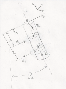
Figure: Secondary shaft FBD
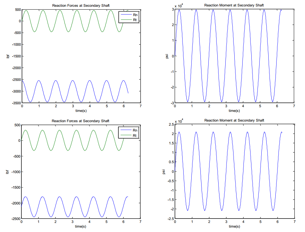
Figure: MATLAB results for reaction forces and moments
Next, a free body diagram of the secondary shaft along with its equilibrium equations would determine the forces acting on the shaft. It was derived by pulling apart the entire assembly and observing the reacting forces and their effect on one another. With an excess amount of forces and limited equilibrium equations, the assembly was deemed statically indeterminate in the vertical direction. The figure entitled secondary shaft in appendix demonstrates the excess amount of unknown forces along the t-axis. The shaft vertical reaction forces at the bearings (An, Bn) had to be neglected. The free body diagram illustrates the forces considered for the analysis. The assumption made the axial force constant throughout the shaft. It can be seen on the FBD that the bolt and bottom plate exert axial forces on the bottom bearing. This would be important to apply design bearing with this load in mind. The top bearing can be assumed to experience no axial load. The tangential forces (Rt, At, Bt) caused a variation in bending moment. The moment diagram for the loading case is illustrated in figure 10 for the modified forces mentioned earlier. Also, the rotation of the shaft was considered for the case when the person is standing direction below the shaft. It was determined that the centripetal forces from the masses offset from the central axis of the shaft would cancel out if the cage is considered symmetrical. Thus, it was assumed that there was perfect symmetry about the secondary shaft and no torsion was induced on the shaft. With the moment diagram and axial load at every point in the shaft, the stresses, alternating and midrange, at points on the outer surface of the shaft could easily be solved for. It was established that there were 3 locations of interest to analyze for safety factors at the outer surface of the shaft. Their respective stress concentration values are listed in table 5. Usually, stress concentration factors are modified by a notch sensitivity value for conservative values but it was decided to assume the shaft had no notch sensitivity for this preliminary redesign. For a more thorough test, this would not be the case.
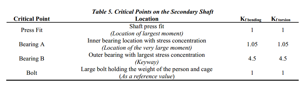
Figure: Secondary shaft critical points
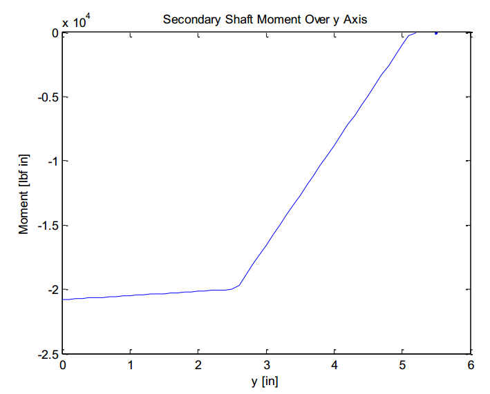
Figure: Moment distribution secondary shaft
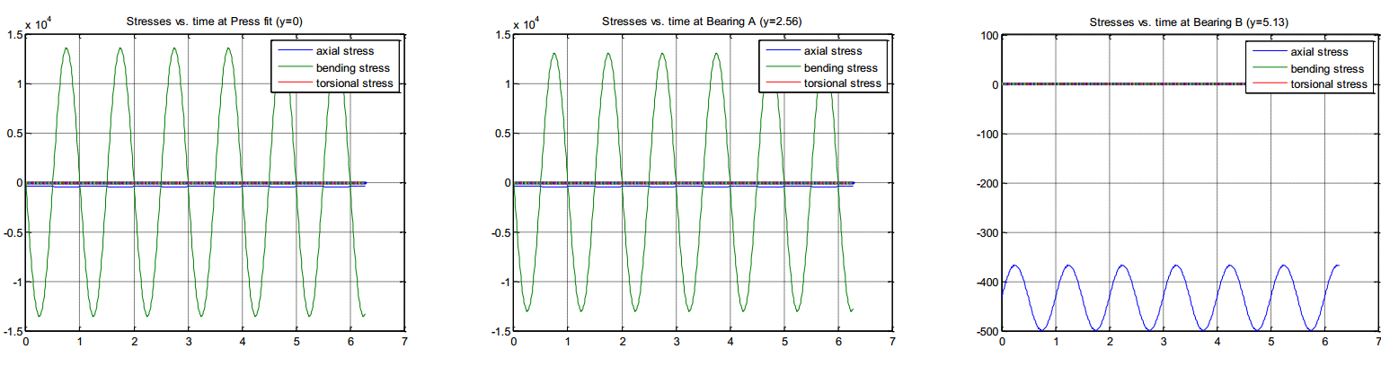
Figure: MATLAB results for reaction forces and moments at critical points
It can be seen from the figure that the bending stresses dominate for the press fit and bearing A while the axial load is the main source of loading for bearing B since it is the free end of the shaft and consequently experiences no bending moment.