"Strive for perfection in everything. Take the best that exists and make it better. If it doesn't exist, create it. Accept nothing nearly right or good enough."
Sir Henry Royce
Delta Robot
Introduction
A delta robot is a parallel-link robot with four degrees of freedom, allowing translation in three orthogonal directions and revolution along a vertical axis. Its base platform is connected to the end effector/tool plate by multiple RUU kinematic chains. With its actuators at the fixed base, the delta robot’s linkages are light and move quickly. The actuators will control the angle of the linkages attached to the base relative to the base plate plane. Its structure is rigid for accurate positioning of its end-effector. The robot is well suited for quick pick and place applications and it is finding use in 3D printing applications.
Tools
- GNU Octave
- Creo Parametric 3.0
- ANSYS
Components and assemblies
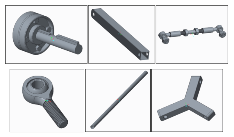
Figure 1: Main components of assembly (a) coupling and keyed shaft (b) upper arm(c) horizontal bar assembly (d) revolute joint (e) rod (f) tool plate
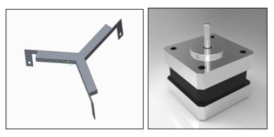
Figure 2: Elements neglected from analysis (a) Base plate (b) Stepper motor
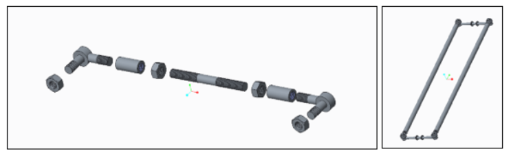
Figure 3: (a) Horizontal bar assembly (b) and its place connecting top and bottom through rods
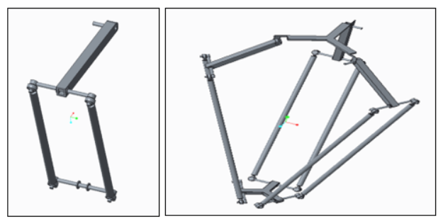
Figure 4: (a) arm assembly (b) full delta robot assembly
Analysis
Kinematic Synthesis
Theory
The objective was to relate motor angles of the upper arm to the position of the end effector. This could be accomplished using the vector representation of the linkages and applying an algorithm defined in [1].
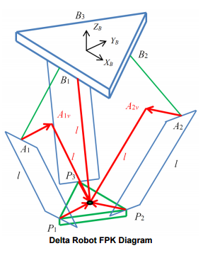
Figure 5: Delta robot vector representation [1]
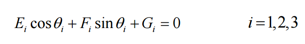
In forward kinematics, the input angles are supplied to the algorithm that solves for the coordinates of the end effector. At this stage, we can modify lengths of the vectors representing the linkage dimensions or the size of the base, to determine valid robot dimensions. Note, if the dimensions were not valid, the algorithm would not output any results, if the dimensions were valid, results were produced as shown in figure 6 (a). Figure 6 (b) illustrates a path defined for input angles following sine definitions.
The Octave code will soon be available on my Github repository @DavidLibera.
In inverse kinematics, the end effector position is specified and the required inputs for the motors are solved. The mathematics requires solving equation below using the Tangent half-angle substitution. This equation and solution method is very common in robotics. Figure 7 (a) shows a desired circular path and figure 7 (b) shows the corresponding solutions for that desired path.
Numerical Results
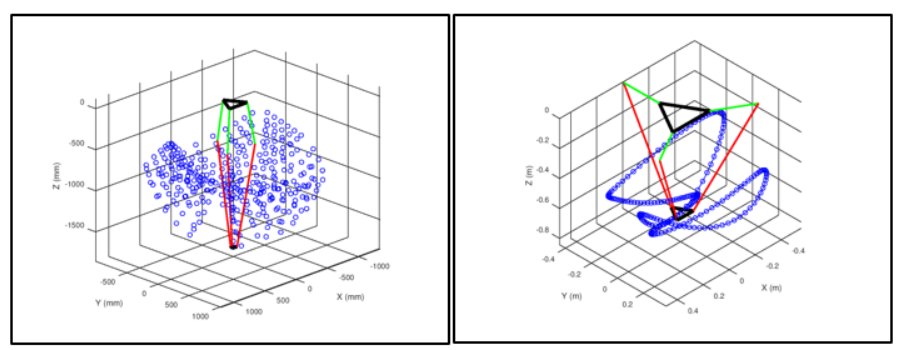
Figure 6: Forward Kinematics results from GNU Octave (a) random angles (b) defined a path
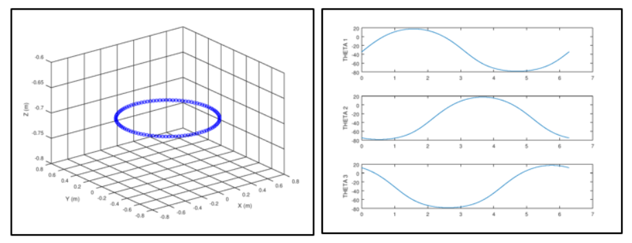
Figure 7: Inverse Kinematics results from GNU Octave (a) Input desired path (b) Output arm angles
GNU Octave was used to investigate the parallel robot’s range of motion and achieve preliminary results. However, CAD software has kinematics capabilities as well. Using PTC Creo, the model was simulated for a motion to its extremity and results are displayed in figure 8. The results confirmed that the desired envelope of operation was achieved.
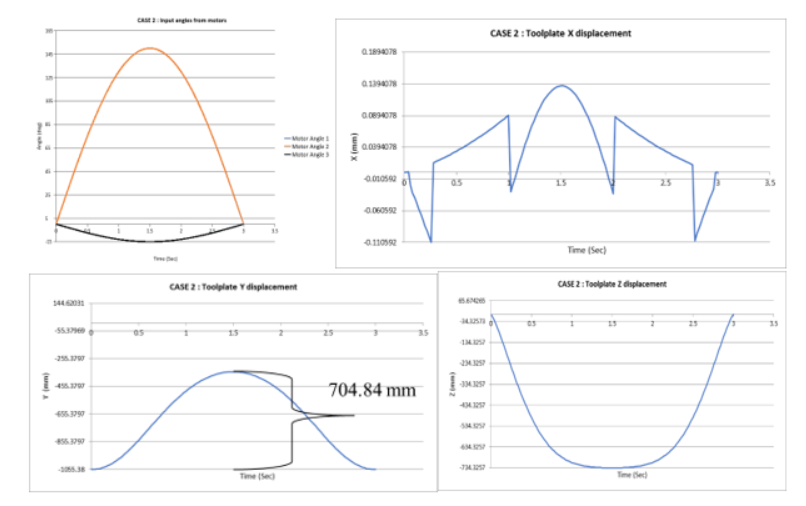
Figure 8: (from top left to bottom right) (a) inputs for kinematics simulation in PTC Creo and corresponding graphs of end effector positon (b) x (c) y (d) z
References
- R.L. Williams II, “The Delta Parallel Robot: Kinematics Solutions”, Internet Publication, January 2016.